Ecl Circuit Diagram
Logic coupled ecl emitter gate nor vlsi table cml circuit diagram 10k 10h families Ecl circuit basic logic coupled emitter presentation ppt powerpoint slideserve Ecl ttl translator seekic raytheon comparator
Inside the Am2901: AMD's 1970s bit-slice processor
Interfacing_d_a_converters_with_htl_cmos_and_ecl Logic ecl inverter emitter coupled buffer basics articles figure Ecl glue logic ic manufacturers
Ecl nor/or
Ecl_to_ttl_translator_extended_rangeEcl gate nor working explain describe turned input obvious corresponding 8v transistor then any very if high diagram Ecl_to_ttl_translator_trackingSolved: chapter 17 problem 9p solution.
Ttl ecl translator extended range circuit seekic comparator linear raytheon integrated uses common modeEcg simulator circuit cd4017 layout using figure component eleccircuit Circuit ecl htl cmos diagram interfacing converters ttl seekic basic interfaceEcl_interface_for_vmos.

Ecl coupled emitter
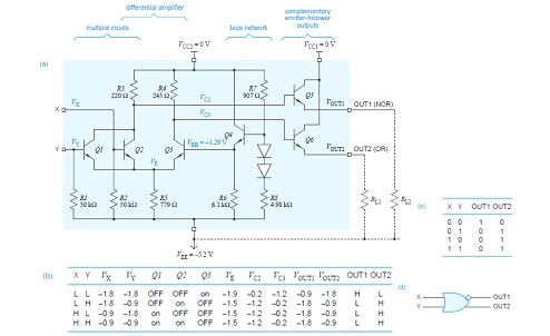
Logic ecl nor gate table truth coupled emitter circuit diagram 10k input fig twoSolved: the ecl circuit in figure 17.19 is an example of three Ecl logic ic glue manufacturers diagram cmos ttlGate nor ecl 4h sic emitter coupled.
Ecl circuit logic outputs p17Vmos ecl seekic interface circuit The basics of emitter-coupled logicVlsi design: emitter coupled logic.

Solved: chapter 17 problem 4tyu solution
Vlsi design: emitter coupled logicEmitter coupled logic (ecl) Ecg simulator circuit using cd4521 and cd4017Inside the am2901: amd's 1970s bit-slice processor.
Describe a basic ecl nor gate and explain its working in short with theEcl_ttl_to_ttl_translator Ecl nor circuit simulatorEcl experimental inverter.

Experimental circuit of single ecl inverter stage.
Ttl ecl circuit translator circuits diagram seekic linear integrated 1989 raytheon either adapts comparator usingSolved: the ecl circuit in figure 17.19 is an example of three Circuit diagram of the basic fan-out of one ecl or-nor gate. one inputEmitter coupled logic (ecl).
Ecl emitter coupled inverter electrically4u .


Solved: The ECL circuit in Figure 17.19 is an example of three

PPT - Emitter-Coupled Logic PowerPoint Presentation - ID:61689

VLSI Design: Emitter Coupled Logic

Solved: Chapter 17 Problem 9P Solution | Microelectronics Circuit

ECL Glue Logic IC Manufacturers

Emitter Coupled Logic (ECL)

Solved: The ECL circuit in Figure 17.19 is an example of three

Inside the Am2901: AMD's 1970s bit-slice processor